
Speedster
Pilgrim
‘Speedster’ Construction Manual.
Intro
The Pilgrim Speedster is a reproduction of one of the most famous open topped sports cars of the 50’s, built to the same exacting standards as all other cars from the Pilgrim stable, the best selling Pilgrim Sumo and the 3000. With many original Speedster parts still available to fit, it can be completed as an exact replica of the original or modified and played with to give you a mean ‘Racetrack Refugee’ look. Engines of many descriptions and power levels can be fitted, from the basic 1300 or 1600 VW engines for the purists, to 2 Liter and above Alfa Romeo engines and onwards and upwards to Porsche engines and beyond for those who don’t scare easily!
There are adapter plates available to bolt practically any engine onto the solid VW gearbox.
Cover yourself with a Hood or try the ‘true brit’ look with a tonneau cover and a leather headset and goggles.
The choices are all yours with our Speedster, the limit is only your imagination!.
The construction of most replica or kit based vehicles is relatively simple. You will however, always come across a few problems here and there that are not mentioned in this manual. Before you go rushing to the telephone to call us, sit down with a cup of tea and think about it, more often than not you will come up with the answer yourself!. If you are really stuck then call us and we will try to help. But remember, it’s YOUR car, you can put in or fit what you like (within reason) however, the sourcing of parts, strip down of donor vehicle and eventual construction of a Pilgrim car is neither rocket science or nuclear physics!. It is a straightforward task which is within the capabilities of anyone who can wield a spanner.
Many people will want to use as many used Donor parts as they can get, whilst others will only want to use new or reconditioned parts. We are able to supply any of the parts that you require, so if you are having any problems sourcing parts, contact us. (there is a list of just some of the parts that we can supply at the end of this manual)
There are some things though, that must be understood before you start.
The Pilgrim Speedster utilises the basic, shortened floorpan of a VW Beetle, so sufficient space will be needed to remove the body from the floorpan. (See later section). Also, VW Beetles were built using 2 very different Steering and suspension assemblies, McPherson strut assemblies and Torsion bar assemblies.
The Pilgrim Speedster (along with all other 356 replicas) can only use a Torsion bar assembly as there is simply not enough space under the wings for the McPherson type.
You are going to need somewhere undercover to do most of the assembly work. The strip-down, ‘grunt’ work on the donor vehicle can be done outside, indeed, even construction can be done out in the open if you do your timing right, but, with the weather here in the UK being what it is, you should keep the covers near to throw over the chassis or car when it rains.
Local Councils have garages for rent at quite reasonable rates, though they don’t have any electricity laid on. Some local Farmers may rent you a small barn Check out your local Yellow Pages under ‘Farmers’. It’s also worth considering what you are going to do with the left over body shell once you have finished with it. Some scrapyards might give you a few pence for it, some might even charge you to take it. You could always cut it up into small manageable parts with the angle grinder then take it to your local tip, though you might have to pay for this as well, though only a few pounds.
Pilgrim can save you all of this hassle with one of our factory shortened and prepared Floorpan units, leaving you to source your own parts etc and concentrate more on construction. We can even offer the chance to have your floorpan Galvanised, extending its life immensely.
Below is a list of basic things which you will need.
You will need (own or borrow !) some half decent tools, including a good set of spanners and metric sockets. These are going to be used most when stripping down the donor vehicle and removing parts to replace or refurbish them. Some specialist tools that you might (note: might, not will) need, are available for rent at any of the hire shops around the country.
You will need a pair (preferably 2 pairs)of axle stands and if possible a Trolley Jack. These are now available from local Car Shops from around £19.99 !!. These jacks are invaluable for removing and replacing the VW engine and gearbox as well as quickly jacking up the floorpan when needed.
An Angle Grinder with cutting blades is essential. ‘Hobby’ angle grinders are up to the job so long as you get one with a rating of 700 watts or above, though, as you might only need one for a few days you can hire them at very cheap rates from most hire shops.
A decent lump hammer and a couple of chisels will also be needed, just in case you can’t get at something with the angle grinder.
WD40 or other releasing agent, a large tin of Gunk or other degreaser and some wire brushes and protective leather gloves and goggles.
If you intend to do the welding yourself as opposed to buying a ready made and shortened floorpan from us, then you are going to need a welding unit. As you might only need one for a few days it would probably be cheaper to hire one.
Finally and most importantly, a Haynes manual for the model beetle that you are using. (See list at end).
If, when reading this guide, you find some things blindingly obvious, remember, they might be obvious to you but not to others, so just bear with us, or jump a few paragraphs.
It is recommended that you read through this build manual completely before starting on the construction. That way you will familiarise yourself with many aspects of the build, and be prepared for certain things when they arrive.
PLEASE BE AWARE, Fibreglass is dangerous, as is the dust from sanded fibreglass. USE GOGGLES AT ALL TIMES WHENEVER POSSIBLE when sanding or drilling the bodywork. Also be very careful when removing and replacing brake shoes and pads, these can contain asbestos, which is also very dangerous
Unless you are going to buy a ready shortened floorpan from us then you are going to need a VW Beetle as a donor car. There are many different beetle models available but ALL use either Torsion bar front suspension or Mcpherson struts, although you might want to avoid early & thus collectable & rusty versions, and some that are (partly) unsuitable. If you want it to be Road Tax exempt then you will need a pre-1972 registered car.
But ! You may not find the engine that you want in the body that is available! This is a common problem.
You will need to contact us or shop around to find the set-up that you require.
VW
Models available
VW
BEETLE 1200, 1300 & 1500 (swing
axle rear suspension, torsion bar front)
Swing
Axle -
The swing axle rear, torsion beam front suspension provides a slightly cheaper
and easier build and also the most authentic set up for the purist.
Chassis
Work Required
- Shortening of chassis.
Other Parts Retained from Donor -
Petrol tank (needs modification), fluid reservoir & holder, steering column,
switches and wiper motor.
VW
BEETLE 1302 & 1303 (independent rearsuspension, MacPherson strut
front)
Independent
Rear Suspension (IRS)
- The IRS rear suspension chassis, which will need to have it's MacPherson strut
front suspension and framehead removed and replaced to accept the earlier
torsion beam suspension, will require more work and sourcing of parts, but
provides the best handling and is the best option.
Chassis
Work Required
- Shortening and conversion of chassis to take torsion beam front suspension.
Additional Parts Required - Complete front beam assembly,
framehead, steering column, petrol tank and wiper motor (if using 1303 as
donor).
Pre-’72 IRS cars are preferable and then a separate Torsion Bar front end unit for several reasons.
1. The IRS rear end units though less original are preferable due to improved traction and stability.
2. These cars can be picked up from the VW mags, VW beetle dealers and wreckers for around the £200 to £450 mark complete with engine.
3. They will have a lot of re-useable equipment on board that will save you many pounds.
4. You should be able to sell many of the things which you don’t use, i.e. doors, seats, windows, engine & bonnet covers etc etc. Selling this lot alone should recoup you about £100
If you prefer and are good at welding, just get yourself a pre-72 IRS donor car and then buy a new front end assembly and framehead and weld it on, and then just swap over the running gear from your donor car.
Try to get one with a 1600cc engine and gearbox, though you can buy Piston and Barrel kits to upgrade the 1500cc engine to 1600cc but you will have to buy a new or second-hand 1600cc Twin Port head. The 1600cc engine is ideally suited as there are many aftermarket products to improve the output horsepower of the beast (more about that later). Front Disc brakes are also preferable to the drum units which will be found on many models, though you can buy a complete Disc Conversion Kit from shops and magazines, Calliper repair kits are usually available also
Before you part with any cash, check the serial numbers of the Engine and Gearbox to make sure that you are getting what you are paying for. AA & AB gearbox serial numbers are 1200/1300 boxes. AS are 1600GT boxes.
As mentioned above, if you are aiming for at least a modicum of originality in your car, you should have settled for at least a 1600cc Twin Port engine or even bigger. Unless you are very lucky, your engine will have come with a standard single carburettor, though you might have been lucky and got one with a progressive opening carb. There are many improvements to the 1600cc engine which can be simply made. One of the easiest is to fit a performance tuned exhaust and a 009 Distributor, the other way is to fit Twin Carburettors. Most of the companies advertising in the VW magazines have new Twin carb kits, ranging from 300 to 500 pounds. However if you wish to save a few pounds, then a few calls to some of the carburettor people around may help you. Second hand Del Orto ‘36’ carbs are available for around £60. Used Webers are around for a similar price.
Most of the VW companies will be able to sell you the relevant inlet manifolds to fit these carbs to your engine, Bugpack do manifolds for most common carbs for around £50 for a pair. You will also need a linkage Kit to connect the 2 carbs, these are also available from Bugpack or the parts dealers, though if you are ingenious you can adapt the Del Orto or Weber linkages if you can persuade the dealers to let you have them.
The 1600GT gearbox is also the one you should be trying to find, though as mentioned earlier these are getting quite rare nowadays, failing that a 1500 or 1600 box will do OK. When shifting gearboxes from one vehicle to another you might come across problems with the front gearbox mounting. Early cars had a 2-bolt mounting whilst later models had a 3-bolt mounting. This isn’t a big problem and the easiest cure is just to find a gearbox nosecone that fits your chassis and swap it for yours, (make sure you buy a new gasket).
Strip Down and eventual refurbishment of parts should be done in conjunction with the relevant Haynes manual or the Haynes ‘Guide to purchase & restoration VW Beetle & Transporter.
The strip down job can be made a lot easier and cleaner if, before you start the strip down, you can get your donor car to a garage and get the engine, gearbox and underbody steam cleaned or at least power-hosed off. Hire companies sometimes rent out this kit so it’s worth giving them a call. Failing that, grab a large can of Gunk and a 2 inch brush from your local car shop, and attack the engine from all angles, including underneath. Gunk is great because it simply washes off with a hose, something that wont happen if you use petrol or paraffin.
If you have the space to keep hold of the dismantled unit once you have taken what you need from it then it would be well worth doing so, as you never know when you might need a piece of steel to weld on here and there, or when you find you actually want something that you have left on it.
If you intend re-using the wiring loom, then buy a roll or two of masking tape from your local car shop and when you disconnect something electrical, wrap a piece of tape around and write down its purpose on the tape.
In this rebuild, the Pilgrim custom loom will be used, for no better reason than it is specifically designed for the Speedster, and will inevitably make a fiddly job a lot easier (see accessory list at end).
Before you start, and a job worth doing last and leaving overnight, is going all over and under the car and giving a squirt of WD40 or releasing agent to EVERY nut and bolt you can find, including all of the steering gear nuts, ball joint units etc, also get a wheel brace and just crack or loosen every wheel nut as its easier to do it now with the weight of the body on the chassis than trying to do it later when the whole unit is substantially lighter. Another job worth doing now is removing the large split-pins on both rear wheels and loosening the central bearing nuts. These are usually done up to over 140 Ft-Lbs, and if you leave this job untill after the body is stripped and engine out it will be very difficult indeed.
Two important things to do first. Disconnect and remove the battery (under the rear seat, drivers side) and put it away safely (you could give it a charge first), then remove the petrol tank. Its under the front bonnet, possibly covered with some carpet or sound deadening material. Remove this material (and everything else in there) and then undo and remove the fuel filler pipe from the fuel tank. Disconnect the wire from the fuel gauge sender unit on top of the tank then undo the securing bolts and washers from the top rear of the fuel tank and gently lift the tank up. Before the next stage, have one or two petrol cans ready with a funnel ready inserted into a can, then disconnect the fuel feed pipe which exits from under the tank. If it is too tight to remove the flexy pipe from the metal line going to the engine then just cut it with a knife and quickly move the tank and fuel line around and drain it into the petrol cans. When the fuel tank has been emptied into the cans, put some plastic bags over the filler pipe and secure with a few rubber bands and also bend the fuel line back and secure it with a jubilee clip or something. Store the tank somewhere WAY out of the way, as there might be sparks in the car if you have to use an angle grinder. It’s also worth wrapping the metal engine fuel line which you have just taken the fuel pipe from with some tape to seal it.
Remove the front bonnet and rear engine cover. Simple job, with just a few nuts to remove, not forgetting to disconnect the wire from the number plate light.
Whilst in the front compartment, remove the two nuts and bolts from the flexi connection connecting the steering box to the steering tube. (leave this in place untill later, its easier).
Have a container ready and disconnect the two brake fluid pipes from the Brake Master cylinder unit below the fuel tank space, quickly slipping them into the container to drain down the reservoir. When this has been done, unscrew and remove the Brake fluid reservoir for later use on the Speedster, along with the support bracket for the reservoir, and the two connecting pipes.
The seats, carpets and any other interior equipment should now be removed and stored for later resale.
Remove the windscreen wipers and arms, and then unscrew the securing screws from the remaining wiper stubs, then the securing screw holding it on under the scuttle plate, and remove and store the wiper unit, (you will need this for the Speedster) along with the wiper switch.
Get the glass out of the way now too, though if you are working in the open you might want to leave the glass to last. Quick way to remove the glass, get a sharp, pointed knife and slip it under the glass rubber from the outside glass side, dig it in, push hard and run it around the rubber. This rubber will then simply pull off leaving you to just lift off the glass, again putting it safe for later re-sale.
If your doors are not rusted to bits, and, if you have an impact driver or have access to one of those garage type impact air guns then you might want to take the doors off for later resale. In reality they will most probably be in a terrible state, and not worth the trouble removing them. Simply wind the windows down out of harms way and leave them there.
Unscrew the front headlamps and sidelights, disconnect the wiring from them and remove and store them for later re-sale, (Label the wires for re-use if you intend to). Repeat with the rear lights.
As mentioned previously, this rebuild will be using the Pilgrim wiring loom which means the existing loom could be left in situ, but if you intend to use the beetle loom it is simply a matter of disconnecting and removing all of the existing loom, from the fusebox, right through to the engine bay, it should all slowly come out, however if you do wish to use the beetle loom then label as many connections as you can, and then remove the complete loom, (it comes off in several sections). You should then remove the fusebox itself, the speedometer unit and any remaining switches.
If the front and rear mudguards look ok or at least repairable, then they may be OK for resale, so first remove the running boards along each side of the car under the doors, then unbolt the mudguards (underneath the guards, wheel side) and put them away. The bolts might shear off when unbolting, don’t worry, they usually rust on tight anyway!.
The engine bay. The nice thing about the Beetle engine is that it comes off rather quickly, however, in our case we can leave it on, and take it off later, which will make the job even easier. Simply disconnect and remove the air filter unit as you might knock it and damage it when lifting the body. You should have removed the connecting wiring when removing the complete loom, but just check to see if any wires are remaining between the engine and bodywork.
Body Removal If you have removed all of the interior fittings, seats, carpets etc, you will have a nice empty space to work in. Now is the time you are going to need the angle grinder. Fit a new CUTTING disc to the grinder and put on your protective goggles/glasses and your protective gloves. Just inside the car at floor level on each side of the car is the combined sill/heater channel. On older cars this is usually rusted rotten inside and it is usually a simple job just to run the angle grinder along the whole length of this from front to back on both sides, though you might need to use a chisel on the section next to the throttle assembly.
Inside the front boot compartment are 2 bolts securing the body to the Torsion Bar assembly which should be removed.
On an IRS car, you will need to undo the 3 small nuts inside the front boot compartment on top of each Mcpherson strut then from below, undo and remove the Track Control arm bolt from the framehead on both sides.
Below, and to the rear of where the back seat was, you will see a line of bolts, which help to secure the body to the chassis, unbolt and remove these. Now, just to the left of the clutch pedal, on the top of the tunnel there is one further bolt to undo and remove, (there might not be one there, some people remove it)
Outside to the front of the car, inside the fuel tank space, two bolts securing the body to the Torsion Bar unit need removing. Round to the back wheels. Just forward of the rear wheel you will see a bolt inset into the rear suspension arm on the suspension unit, remove this and also do the same to the bolt on the opposite side of the car. OK, final leg!. Underneath, forward of the front wheel on the framehead there are 4 bolts, 2 each side which need unbolting and removing. If they come off, then ok, if they wont then don’t worry as the inside bodywork attachment will most probably be rusted off anyway. Again, underneath and along each side of the car you will find a row of bolts securing the chassis to the body. These can be difficult to undo as they are each seated in a large washer, they will also, if you have a pre-72 car, almost inevitably tear loose inside the heater channel from the rust, don’t worry!. Practically all beetles will have had their bodies welded to the chassis along the body/chassis edge. This is where we need the angle grinder again, this time changing to a Grinding disc as you will need to go along each edge and grind off the welds. Just grind off sufficient to separate a small section between the upper body and chassis and then hammer a nail or wedge between the two sections. Continue grinding off the welds and as you move along the two halves will pop apart. You might need to move the wedge along from time to time, but it will eventually come free.
Hopefully by now the body will be completely loose and free from the chassis. This can be tested by putting a jack under the front of the car and jacking up the body, you should see it lift from the chassis. This should be tried on the back end of the bodywork too, to check that all is free.
This is where your friends will come in handy!. 4 People should safely be able to lift the body from the chassis. Failing that the job can also be easily accomplished with a block and tackle lifting the body up and then rolling the chassis out from underneath. It can also be done with two people by first jacking up and then blocking up the front of the car, then lifting the rear of the car and again rolling the chassis out from under. Good Luck!.
RENOVATION
There are many different stages of renovation depending on your pocket and the parts that you intend to re-use. This manual will not begin to advise you on which parts are, or are not serviceable. That will be your decision, though replacement of most of the relevant parts with new will not be too expensive if purchased when required.
However, with relevance to the chassis you are never going to get access to some of the more difficult parts as easy as this again, so make the most of it.
All of the brake parts should be discarded and replaced, though if the brake shoes are ok they may be used, but at about £18 for a new set it is hardly worth it.
You should now have a rolling chassis, with an IRS vehicle you will need to support the front with a trolley jack.
Remove all of the brake pipes and discard them, (don’t forget they will have some brake fluid in them!). But keep hold of the Brass ‘T’ junctions for later use.
Refer to your Haynes manual and remove the handbrake cables.
Now is the best time to remove the engine (if you haven’t already done so), followed by the gearbox. Grab your Haynes Manual and follow the instructions. It isn’t difficult. Separating and removing the engine from the gearbox now should take no more than 20minutes. Take off the gearbox complete with the drive shafts/tubes. You will need your axle stands to support the chassis.
Once you have the engine and gearbox off of the chassis, remove all of the remaining control cables, Clutch, throttle, handbrake & heater cables, remove the handbrake lever for later use, along with the heater controls alongside it. Two bolts secure the gearlever, remove these along with the lever itself. Undo the access panel on the front of the tunnel and disconnect the gear leaver actuating rod and then remove it through the hole at the front of the tunnel.
Now VERY importantly, remember that you have the fuel pipe, running from front to back inside the central tunnel ?, well this will still contain some petrol, and this little bit of fuel must be removed before any attempt is made to cut the floorpan. You could put the front piece of pipe into a can and simply blow through the engine end untill all the fuel is out. You can do the same thing with a footpump or even a bicycle pump.
Its now worth removing the front Torsion bar unit as a lump. Or remove the McPherson strut steering assembly with the aid of a trolley jack.
With a Torsion bar system you will have to disconnect the steering control arms first, after that it is a simple job to undo the four bolts holding the Torsion bar unit on, and let it roll forward onto the ground. You might find it easier to remove everything from it first before actually removing it, as you will be more able to put tension on all of the bolts etc.
It is now advisable (unless the actual floorpans are in superb condition) to remove both the floorpans. Firstly you will need to chip off the very thick sealant between the central tunnel and pans then using a either a spotweld remover or a simple brick bolster and hammer detach the old floorpans from the central tunnel.
Shock Absorbers. As the Speedster body is considerably lighter than the VW body, you are not going to need uprated Shock absorbers, the standard VW units will suffice.
If replacing the front torsion unit with one from a wreckers, check carefully around the ends of the Torsion Bar tubes as these are prone to rust and can be welded up quite cheaply OR buy a new complete Torsion beam assembly from ourselves which will come complete with lowering adjusters. Check all Ball Joints & rubbers.
It’s really worth replacing all of the wheel bearings whilst you have easy access to them
Chassis shortening and refitting
Floorpan modification is one of the most important items of a Speedster build. It involves cutting and shortening the 2 floorpans and central tunnel without cutting the tubes inside, shortening the sections by approximately 275mm and then re-welding the lot back together again, keeping all of the alignment true.
One
very important point to note is that on certain models the hand brake was
situated slightly further back and if you don’t check the measurements of
where the sub-chassis locates onto the front and rear of the
floorpan you could find it is 3 inches or so too short!. This is especially so if mating an IRS rear end to a torsion
bar front end.
If you are not happy with doing this work or are not competent at welding then you have several choices:
· Buy a ready shortened floorpan from us
· Bring your stripped floorpan to us for modification
· Get a garage or a competent welder to do it for you ( but again make sure you get the measurements correct)
When shortening the floorpan it is very important to weld and
align the tunnel back together correctly to restore the structural integrity of
the whole thing. If a fibreglass body is bolted to the frame it regains some of
the original characteristics but it is not nearly as rigid as the complete VW
Beetle. This rigidity is returned to the floorpan by the bolt on Sub-Chassis
assembly. A MIG welder is
recommended for the welding, an arc welder is not recommended because it will
probably just melt holes in the metal. Brazing is not acceptable. It is also
very important to keep the alignment of the frame intact. Spend more time
measuring for accurate alignment than welding !.
If you
intend doing it yourself then use the attached cutting plan as a guide,
remembering that the tubes inside the tunnel for the throttle cables etc, need
to be rejoined, though this can be done by finding slightly larger tubes and
securing these over one end and slipping the other end over the matching tube as
you re-align the body for welding
The 2 actual floorpans themselves are quite thin metal and will be easy to cut and remove, however, the tunnel section is 3/16”
steel and will take a little time.
If you haven’t already done so, remove the rear central tunnel access panel and disconnect the gear change rod and remove the universal joint on the end of the tube. This tube can then be pushed forward and removed though the small front access panel on the front framehead. Cut and shorten this by approximately 275 mm. This can be made easier if a piece of pipe of the same internal diameter as the tube can be found.
You will then need to chip away the Tar-based sealant material which covers the central tunnel and seam join areas. Tapping gently with a hammer will remove most of it. If you are retaining the two floorpans then you will need to cut the floor as a whole as in the diagram. If, as we recommend you are also replacing the two floorpans then proceed as follows: Remove the two floorpans completely, this includes removing the spot welds from where they are attached along the central tunnel. This can be done with a purpose made Spotweld remover, a drill or just chiselling under the two panels with a large brick bolster. Be carefull not to damage the central tunnel too much. The replacement floorpans can be cut later then laid onto the shortened central tunnel and welded in.
With the floorpans removed access to the central tunnel for measuring, marking and cutting is made easier.
Below is just one of several methods of shortening the Tunnel section. Another method is a straight cut across and even another is a staggered or castellated cut. The one thing to ensure is the setting up of the whole thing and constant measuring before, during and after cutting and tack welding. Only after the pans are completely true should the be finally welded up.
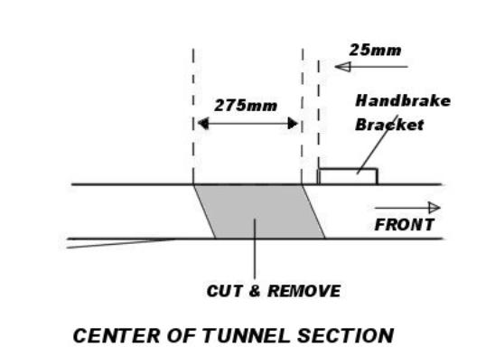
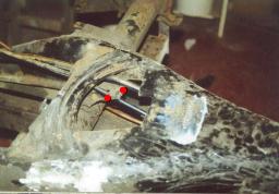
Mark 2 lines on the central tunnel 275mm apart, starting about 25mm behind the handbrake unit. Cut gently and not too deeply, as you will be trying not to cut the control tubes inside the tunnel. On some tunnel sections, the cuts will need to be angled back to avoid cutting into the widening section of the rear ‘wings’. Once the vertical cuts have been made, cut horizontally along between the vertical cuts and remove the complete section, leaving the underneath section intact for the moment. Retain this removed section as the seat belt anchorages will be needed later. With this 275mm section removed you will be able to see the internal control tubes.
Control tubes
You will now have two sections of central tunnel with the control cable tubes running through the gap.
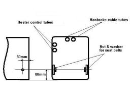
Locate the two heater control tubes which run from the heater control beside the Handbrake and pass out inside the car and cut them, These are not needed and can simply be bent away and secured to the other pipes to avoid rattling.
The fuel pipe can be cut and removed or bent back and secured as it would be prudent to replace it with a complete new section. CUT THE FUEL PIPE WITH A HACKSAW as there may still be fuel in the line and an angle grinder could ignite it. You can replace it with new copper pipe running inside the tunnel section. It can be difficult feeding the fuel pipe back through the tunnel and out of the original hole. One way is to feed a small wire down through the hole and along the tunnel section, then attach some flexi pipe to the end of the petrol tube, the flexi to the wire, and pull it back through. Alternatively it can be run alongside the brake pipes on the outside of the tunnel
Locate the 2 handbrake cable tubes. Break away the spot welds securing them to the handbrake assembly and shorten by 275mm. When mating the front and rear tunnel section loop some wire around these for use later. (See later section)
You will need the 2 heater control tube on one side as these carry the control cables which run to the two heat exchangers and turns them on and off. These can be cut, shortened by 275mm and be oversleeved with some of the waste clutch tubing.
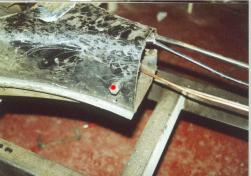
Finally the Clutch and Throttle cable tubes will need to be cut away from the securing bracket through the rear access panel as shown below. The stubs will need to be removed and when joining the two section the clutch and throttle tubes put back through the holes and cut to length.
The remaining stubs need to be cut away and removed as the remaining clutch and throttle tubes will pass through the holes after shortening.
The underneath section can now be cut, firstly ensuring the two halves are supported.
The cut sections should now be cleaned up with a file as angle grinder cuts are not clean and leave an angled edge on the inside of the cuts.
The Seat Belt anchoring point can be cut away from the removed tunnel section and drilled and welded into the rear section of tunnel, or as below the correct sized nut can be welded to a large washer or small steel plate and then drilled and welded into place.
 …
…
Before drawing the two halves of the tunnel together insert the 2 handbrake cables into the tubes and pull them through as this will help align them before welding up.
Just behind the handbrake assembly cut a small section out about 1” wide by ¼” deep. Pass the wire through this gap and pull up on the two handbrake cable tube and gently weld them into place through the hole.
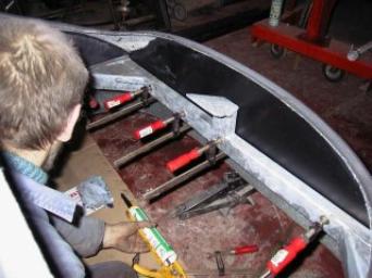
Bring the two chassis halves together. While doing this, guide the tubes for throttle and clutch into their bracket and holes at the rear of the chassis. (see fig.A)
Before welding the central section in, ensure correct alignment all around . This can be helped by clamping angle iron or wood to the channel edge of the tunnel and then checking the measurements on each side. Tack weld in several places first then check alignment before continuing. When tacks have been placed all around the join and alignment checked, then 3 inch welds should be made along the seams leaving 3 inch gaps, then as you move around fill in these gaps with weld. This will stop the generated heat warping the sections.
With the new floorpans, remove a 255mm section as per the cutting plan. Offer these up to the welded and finished tunnel sections. Use the existing bolt holes in the pans as reference points and REMEMBER: Don’t weld up untill you have tack welded and measure several times. When rejoining the pans, measure and overlap them by 20mm giving an overall shortening of the pans of 275mm. It is preferable if you can lay a piece of wood above and below the pan sides and clamp them up as this will ensure the pans are welded up flat. Tack weld the 2 halves of the pan and then measure again before finally stagger welding them up. 2 inch welds-3 inch gap
DONT FORGET TO WEAR PROTECTIVE GOGGLES, you cant replace eyes !.
After the 2 sections are securely welded together, seam sealer should be put on all the welds, then any unwelded joins and gaps between welds sealed with Sikaflex or similar. It would also be a good idea to go over the chassis welds and gaps sealing up all gaps. Finally Hammerite followed by a coating of sealant using a Schutz gun will provide good protection, but underseal spray available from car shops will do fine. You might also want to spray inside of the central tunnel with Waxoyl or similar, as this area will be sealed off once the 2 sections have been joined.
You should now be ready to fit all your new brake pipes and ‘T’ junctions, throttle cable and shortened Clutch Cable. Measure the length of the brake pipe from the ‘T’ piece on the top of the rear torsion bar, forwards alongside of the tunnel section, through the front bulkhead and round to the Master cylinder position on the pedal assembly. Allow a few inches extra. Brake pipes can them be mad up by your local car accessory shop or can be made up yourself using one of the brake pipe flaring kits on the market. Run the brake pipe for the rear brakes in its original position on the tunnel side, securing with the small flaps or welding on new flaps to bend over them.
All pipes should be secured to the body with ‘P’ clips or welded on, fold over clips.
Before putting the body back on and securing it down, give all bare metal and welded parts a healthy coating of Hammerite or Underseal.
Check, and make yourself familiar with all of the separate pieces which have been supplied. If you are in doubt over any part then call us and enquire. It cannot be emphasised enough that the final overall fit of the various parts of the assembly, bonnet doors etc, depend on correct fitting. This is achieved by constantly checking measurements and fit, time and time again..
The following work needs to be done in the order printed below. Jumping a section could mean you will have to drill out and re-rivet some sections.
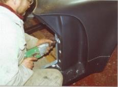
Both the bonnet and boot lids are supplied with the edges untrimmed. If using an angle grinder to trim them back, GREAT CARE SHOULD BE TAKEN. Angle grinders will slice through GRP like a hot knife through butter and if using this method then only cut the untrimmed edges back slightly and finish off with a coarse file or sandpaper and finally wet & dry paper.
The complete bonnet latch assembly is taken from a VW Polo. A hole for the central latch and for the 4 securing rivets will need to be cut and drilled using the recessed area on the body. Position the latch from underneath and then secure with 4 large Pop rivets.
The bonnet section can be inserted into the lock and then the holes marked onto the bonnet for drilling and securing. The release cable then attaches to the release mechanism and is fed around the inside of the boot area and through the front bulkhead on the passenger side with the actual release handle itself fitted in the passenger footwell area or where desired.
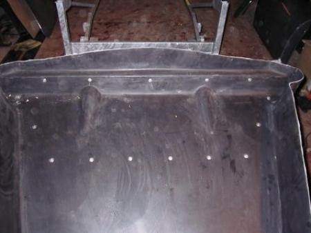
Inner
Tray fitting.
The fitting of the inner tray cannot be done correctly until the bonnet edges are trimmed down and sanded to their final state.
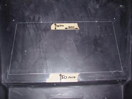
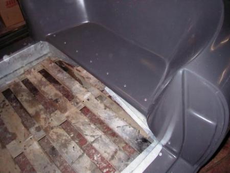
Mark and cut the petrol tank aperture. Mark a line 50mm up from the edge of the top lip of the tray, then another 365mm up from the first line. Then as centrally as possible measure two lines 700mm apart. (see photo) and remove this section completely.
A hole should be made in each rounded corner to take the demister tubes and the tubes bonded in with either GRP or Sikaflex
Ensure the tray is centrally positioned and rivet into place.
Once the inner tray is fitted and secured and the bonnet lid trimmed, then continue as follows.
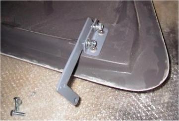
Locate and Pop rivet onto the bonnet the two hinge base plates, then attach the ‘L’ shaped hinge bar onto them followed by the internal securing posts When this is done you may need some help. It will help if the body and sub chassis are raised up off the floor. Get inside the front bonnet area, then have someone place the bonnet correctly and ensure it is evenly gapped all round. (if you are doing this alone you should secure the bonnet in place with Gaffer tape and then adjust to fit after) From inside the bonnet area lift the two hinges and securing posts into place on the inner tray and mark the holes for drilling. The bonnet and hinges may then be removed and the post holes drilled into the tray and the support posts bolted into place.
The inner tray will then need to be trimmed to fit. Place it in position and then looking under the body where it touches, mark the edges that are touching the body and trim down. You may need to do this several times before the body sits correctly on it.
The inner tray should only touch the body very lightly (if at all) as if it does it could distort the bonnet opening meaning the bonnet (and later on the doors) will not fit correctly
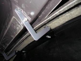
Once the body is sitting correctly over the inner tray, the two front support posts can be placed in situ over the two lugs on top of the torsion bar and loosely secured. You will then need to mark the hole positions where the upper lug sits on the inner tray and then drill. Check for correct fitting but do not secure into place as the body will need to be removed one more time.
Before the body is finally secured into place, holes will need to be drilled into the body on both sides behind the ‘B’ post and the sub chassis marked through the holes. The body will then need to be removed and holes drilled through the sub-chassis. You should screw the seat belt bolt through the hole into a correct sized nut and the nut carefully welded into place (not forgetting to remove a little of the galvanizing first.)
Bottom seatbelt Attachment.
When all of the above has been done and you are happy, the body should be carefully repositioned above the sub-chassis.
Body on
Before
placing the body onto the shortened floorpan, an original VW body gasket should
be shortened and placed onto the floorpan. Sufficient flexible sealant (NOT
silicone) should be liberally applied to all the mating surfaces and, when the
body has been securely attached to the sub-chassis, the complete body and sub
chassis assembly should be positioned onto the shortened floorpan.
Working from
underneath, and moving around the floorpan, drill through the sub-chassis using
the holes in the floorpan as guides.
Moving to the
front of the floorpan and again from underneath, locate the two holes on each
side of the floorpan front arch and with a marker pen or scribe, mark the
position of the two bolt holes onto the chassis and then repeat the procedure
with the other side. The sub-chassis should then be removed or lifted up high
enough for these holes to be drilled.
The floorpan gasket should now be located and cut to size. Before placing the gasket onto the floopan, copious amounts of sealant should be placed all round the floorpan mating face, then carefully position the rubber gasket and then once again place sufficient sealant to ensure a good seal before finally placing the body carefully onto the sub chassis.
The front end should then be secured with two nuts and bolts on either side, though don’t tighten the too much at the moment.
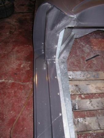
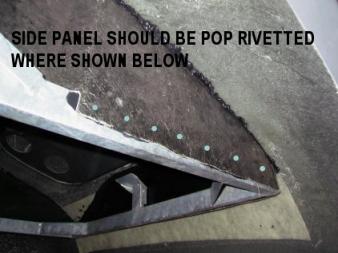
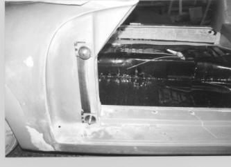
Moving to the rear, underneath and behind the ‘B’ posts, insert the four long bolts and plates each side through the four small box sections into the holes in the rear floorpan units. Finally, ensure that the whole body is centrally positioned then tension the four front and rear bolts and drill and pop rivet the sill, seat and ‘A’post as shown in the photographs.
Finally, secure down the front inner tray onto the posts.
When this has
been done, you will need to go
around all mating and joining surfaces with a sealant gun, (preferably Sikaflex)
ensuring there is nowhere for water to enter. Pay particular attention to the
joins between the inner tray and body underneath the wheel areches and under the
dash. You will now have a complete rolling bodyshell.
 ..
..
Ensure the ‘A’ post GRP upright and the chassis upright measurement are equal on both sides before riveting
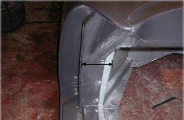
Rear Rivetting positions.
CLOSING
PANELS
If you have already fitted your engine onto the gearbox and floorpan then you will need to fit the engine bay closing panels before you fit the body/sub-chassis to the floorpan. If not it can be left until after the body/sub-chassis is fitted but it is much more difficult.
The rear closing panel behind the engine lid lock support will need to be fitted by drilling through the sub-chassis securing with nuts and bolts before bonding in with a sealant/adhesive such as Sikaflex, All the others need to be pop riveted to the sub-chassis first and then bonded to the body with Sikaflex after trimming to fit.
An access panel will need to be cut into the rear bulkhead area. Use the supplied GRP box section as a template and cut out the panel. This supplied box section can then be trimmed to fit and fibre-glassed into position When this has been fitted correctly the rear engine bulkhead can be glassed into place over this, effectively sealing off the whole of the engine bay from the forward passenger compartment. . This last closing panel needs to be fibre-glassed in securely as it supports the hinges for the engine lid.
When this last panel has been bonded in securely, the hinges for the engine lid may be firstly attached to the engine lid and then after lining the engine lid up correctly, bolted through the bulkhead.
The panel which was cut out can now be fitted back into the hole from whence it came and secured with two small hinges inside, not forgetting to gently countersink the GRP so the screwheads lay flush with the surface. 4 small blocks of wood will also need to be screwed around inside the opening to prevent this small door from falling back through. A small fingerhole can be drilled into it at the top to allow it to be pulled open.
Doors
Door fitting
can be a tedious task but extra time and patience spent here ensuring a good
gapping all around between the body and doors will pay off. Many a fine car is
spoiled by ill-fitting doors, so patience, adjustment and time is of the essence
here.
The holes
drilled in the door should be slightly oversize to allow the door to be
positioned correctly within the door opening.
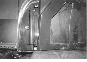
Refer to the
picture of the door. Mark and drill one hole 60mm up and 35mm in from the bottom
and side of the door opening. Now mark a lin 370mm up from the first line and
45mm in from the edge and drill another hole.
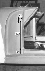
Now refer to
the picture of the ‘A’ post. Mark a line and drill a hole through the GRP
and also through the steel Hinge support bracket behind the GRP, 65mm up from
the sill and 45mm in from the edge of the ‘A’post. Mark and drill another
hole 320mm up from this and 45mm in. Finally, bolt the hinge unit through the
GRP and steel support bracket using the supplied spacers. Repeat procedure for
the other side.
 ..
..
Place the
door in position within the door opening with the hinge bolts locating into the
holes. Using the two large washers and nuts supplied, attach the door to the
hinges but do not tighten down completely. Tighten sufficiently to hold the door
but also to allow movement if needed. Using either cardboard, paper or whatever
is at hand check that the gap all around the door is even.
If necessary,
the gapping between the back edge of the door and the ‘B’ post can be
adjusted somewhat by gently raising or lowering the rear of the car with a jack
and then fixing the position by use of the two adjusters on either side of the
chassis which secures the rear of the GRP body to the chassis.
Final depth adjustment (if needed) of the front of the door may be
achieved by placing small shims between the door hinges and the actual door.
Once again this can be a difficult job, achieving a perfect gap all around the
door, but just take your time.
Once the door
is opening and closing satisfactorily you will need to cut and attach the door
opening mechanisms. Use the cutting template.
Instruments
Lighting and Electrics
Fitting the wiring loom. The Pilgrim loom is made specifically for our range of cars but at first appearance may look like an impossible job to fit. If you feel it beyond your capabilities then consider getting an Auto-Electrician in to do the job. The actual fitting, if used with our wiring plan is quite simple and straightforward.
You may find it easiest to first lay out the loom on the floor, and then using the wiring chart and some masking tape, label most of the wires, i.e. front left and right headlight & indicators, rear lights & indicators etc etc. It is then simply a matter of drilling a hole in the front upper bulkhead and feeding the wires through, and a hole in the rear tunnel section for those wires. Where all wires pass through bulkheads, use a grommet to prevent chafing finally waterproofing with sealant to prevent water ingress..
The rear sections of wiring loom should be secured to the chassis rail with ‘P’clips and cable ties. Use the original headlight relay from your VW donor car, our loom is designed for it.
Again, if you feel this job is beyond you check in you local yellow pages for an Auto Electrician.
As this is a GRP vehicle, special attention should be given to ensuring every piece of electrical equipment is sufficiently earthed. There are sufficient (black) earth wires in the loom but if in doubt, connect a spare black wire to one of the securing screws on any of the electrical items and connect it to the chassis (self tapper)
ATTENTION !. Please ensure you have the correct regulator for your model of Generator.
There are two for Generator models , Check before connecting.
There are
several different Instrument configurations possible for a Speedster, however
the most usual being the 3 large instrument set. You would have specified this
when ordering your kit and the holes will be ready cut for your chosen
configuration. The 3 instrument set consists of a Speedometer, a Tachometer and
the final instrument containing the engine and oil warning lights, and fuel and
temperature gauges. These need to be fitted before the Steering wheel and
steering tube assembly is bolted on as it can be difficult after. The two holes
for the indicator warning lights should also be drilled before securing the
steering column. When you have decided on which position to install your Speedo,
you will need to mark the position where the speedo cable will pass through the
bulkhead and drill a hole. The hole size should be large enough to take the
cable and also to be sealed off with a grommet.
The Steering
column can then be pushed through the bulkhead and attached at the bottom to the
steering box with the flexible ‘donut’ and at the top end with two nuts and
bolts through the bracket attached to the steering column and onto the bracket
under the dash on the sub-chassis. The thick rubber steering column sealing
grommet that you removed from the donor car should also be pushed down into the
hole through the bulkhead to seal it.
The wiring
loom should be attached up behind the dash and the connections made to the
relevant instruments. Attach the two relays securely but place them somewhere
accessible as they mat need to be changed from time to time. The complete loom
should then be laid down alongside the sill on the drivers side and secured with
‘P’clips.
Headlights
and Horn Grills
NOTE: Your
body work is made of GRP which does not conduct electricity so ensure an earth
wire is connected to every light fitting and then run and attached to the
sub-chassis.
Attach the
headlight securing lug inside the top part of the headlight aperture. This is
done by placing it in situ, marking and then drilling a hole to finally secure
the lug with a self tapping screw. Using the supplied template and instructions,
mark out the Horn grill apertures and then with a Jigsaw cut out the hole and
secure the grill. For the indicators, only a small hole will need to be drilled
to allow the rubber gaiter to pass though the bodywork
Rear
Lights and rear reflectors
If using the
teardrop rear lights, refer to our measuring guide and template then mark out
the aperture and cut. Finally screw the light into place. The number plate light
is fitted as above via the measuring guide. Ensure the wires behind are secured.
Windscreen wipers. The Speedster needs the windscreen wiper unit with the ‘Coke Can’ type motor, rather than the rectangular aluminium one. It will fit quite easily in the same place that was fitted on the Beetle though may want to fabricate a small bracket to help support it.. You may wire up the wipers to utilise either twin speed or single speed, depending on which switch you use, and connections on the wiper.
The windscreen washer bottle is attached on either side of the front inner tray though if it is a large one it will need to be fitted in the front section behind the spare wheel.
You will need 4 sections of 5/16th flexible brake hose and a length of 5/16th brake pipe. Two sections fit onto the reservoir pipes and two onto the inlet tubes of the Master cylinder
Your brake fluid reservoir should be fitted on the inner tray wall, passenger side using the tray removed from your beetle.
Two holes need to be drilled below the reservoir, then attach the two flexible hoses and feed them through. You will need to measure, cut, and then attach and secure the brake pipe to the flexibles on the reservoir and master cylinder.
PRE-
SPRAY
If you are having the body sprayed rather than polishing up the GRP then it is advisable to pre-drill and fit all the external fittings, i.e. Lights, horn grills, bonnet and door handles, side brightwork and badges etc. etc. before removing them for the actual spray job This needs to be done to avoid any problems damaging the paintwork after spraying.
When sanding and flatting down you may find many places which need filling, mainly where the mould sections were joined, for this use P38. For some of the smaller pit holes and scratches use a specialist filler which comes in a tube and which can be obtained from a spraypaint supplier. See final sections on GRP for detail.
Fit the frame rubber to the glass first and then fit the frame. You can make the job a little easier with the application of a little soapy water, but it is a tight fit. Fit the bottom rubber, then secure the frame to the support posts.
The window frame is chromed brass, and will be drilled and tapped to screw straight to the support posts.
Ensure that the dash trim, demister
holes and demisters are fitted before fitting the windscreen as it is
impossible to fit these once the windscreen is secured.
The windscreen should be completely assembled with the side posts and hood fitting brackets. It should then be placed into position on the body (not forgetting the small rubbers under the sideposts) and the center tensioning post attached to hold it in place. The spacing tubes should then be slipped over the post from below and then the washer and finally the bolt. Place both spacing tubes and bolts on loosely first and then tension down little by little, easing the bottom rubber into place.
Once the windscreen is secured down you may wish to insert some sealant under the front rubber (unless you did this whilst fitting it) and then finish off with the chrome insert strip.
Many types of seats are available for the Speedster. Fitting is straightforward.
Attach the runners to the seat base with nuts & bolts ensuring the runners are parallel. Attach the bottom runners. Position the seat centrally (sitting in it will help to stop it sliding and to better judge position. Then release the lock and slide the seat back on its runners until the securing holes can be seen and mark through the holes onto the floor. Drill these holes and secure the runners down with nuts & bolts using a large washer on the underside of the floor, then slide the seat forwards on its runners until the rear securing holes can be seen and again, drill and bolt the seat runner down once again using large washers on the underside. When both seats have been bolted down it may be wise to seal around the washers and bolts with sealant to prevent water entering
General
strength and Handling.
The body mouldings are manufactured by Pilgrim to a very high standard in order to keep to a minimum the amount of work needed, on the part of the builder, to achieve a very attractive and well presented car. The overall lay-up is 1250 grams per square metre with additional material around the fixing points and potential stress areas, Steel frames and plates are bonded into the mouldings where required.
Whilst the gel-coat surface of the mouldings are a good deal more scratch resistant than standard paint, it is a wise precaution to protect them during the build up with old blankets, polythene etc.
We recommend that the underside of the wheel arches be painted with a standard undersealing solution
This will help protect the underside from stones thrown up from the road.
When handling mouldings (particularly from the underside) you are advised to wear protective gloves to avoid getting fibreglass splinters.
Fixing
to and riveting fibreglass
Wherever fixing takes place through the G.R.P. bodywork, either to the chassis or for fixing of trim we strongly recommend the use of load spreading washers, even where the body itself has been reinforced. When screwing through a fibreglass panel from the gel-coat side you must countersink the hole to avoid cracks in the gel.
Flash
line removal.
A significant portion of the strength in the bodywork is provided by the returned edges, which are achieved in the moulding process by use of separate removable mould pieces. These create a seam or flash line where they meet. On bodies which are to be painted they are easily and quickly removed using an orbital sander with 280 grit discs. Removing flash lines to preserve the gel coat coloured finish is a more time consuming process. It is almost impossible to remove all traces of the flash line. Please read our document entitled Gelcoat or Paint.
Firstly, using a fine cut flat file take off the bulk of the flash, taking care not to cut into the surrounding gel-coat. Then with a scraper, which can be made by polishing the flat edge of a hack-saw blade on an oil stone, scrape back until the line is almost flush with the surrounding gel-coat. Next, using 1200 grit wet-or-dry paper with water and on a block, cut back until the line disappears and blends with the surrounding body.
Finally, with a coarse cutting compound, such as Farecla G.7, either by hand or with a mechanical mop, polish out the remaining cutting marks. Although flash line removal is basically a simple task it does take a very long time to do well.
Our experienced staff take 2 full days to de-flash a body even with the correct materials and equipment.
The flash line is a week point on the mould. Pieces chip off it over an extended production run. Each time a moulding is made, these "chips" are filled with plasticine, which come off the mould and show as white marks on the body. They can be removed with a little soap and water.
To achieve an overall high gloss finish on the bodywork simply polish with a compound such as Farecla G.7 followed by G.3 on a soft sheepskin or nylon foam mop. Compounds such as T-cut can be used but take much longer to bring a shine to the body (because fibreglass is a good deal harder than paint)
Take care not to overheat local areas of the G.R.P. with the mop as this can cause discolouring of the gel-coat. We find sponge head mops are much easier to use than the sheep skin type and are much less likely to overheat. Always refer to the instructions given with whichever compound you have chosen. Do not leave large wet areas of compound on the body for long periods because the ammonia in the compound can cause the moulding to change colour.
Accident
damage.
Minor scratches in the gel-coat can be removed in the same way as flash lines. Deeper scratches or cracks require digging out and filling.
Larger
repairs
These may have to be done with an ordinary body filler on the surface, reinforced with glassfibre laminate on the underside. The repair then has to be spray-painted, the colour can be matched by your local car paint specialist.
Serious
damage repairs.
To repair larger damaged areas, sections can be moulded in our mould to replace the section damaged on the car. The new section can be fibreglassed into the existing bodywork and the join line filled. It is then sprayed as above.
Body
Storage.
If you intend to store the body for a long period whilst you are working on the chassis, it is advisable to put it in a shaded area. If covers have to be employed they must be of canvas material not polythene. Polythene covers can and frequently do cause the surface finish to be damaged.
Drilling
and cutting fibreglass.
It is best to use drill-bits with the cutting edge backed-off (This is because fibreglass is less prone to being chipped if it is cut with a scraping action). If you have difficulty in understanding how to back-off a drill bit, then use a blunt drill instead. Use at low revs where possible, drill through the gel-coat side to the laminate side. Hole saws are very useful, but again, use low revs. A hacksaw is also very useful, especially when fitted with the tungsten carbide file type of blade which will cut in any direction and will not chip the gel-coat. Jigsaw blades are also available of the tungsten file type. A pad-saw, fitted with a hacksaw blade can also be used where a full hacksaw is denied access.
When cutting, grinding or sanding fibreglass, it is very important that you do not inhale any airborne dust particles. You should always wear protective breathing apparatus.
Pin
holes.
Gel-coat is a porous material, viewed under a microscope it appears to be like a sponge. The size of each hole in the structure is usually very tiny but, depending on how the gelcoat has cured, can have a few quite large (up to 2mm diameter) pinholes. When sandpapering or polishing the fibreglass to remove the flash lines or scratches etc., you may expose some of these holes. When polishing they fill with compound and show as white spots.
To eradicate these pinholes you have three alternatives:
a) Dig out each hole and fill with gel-coat (available from us) and then treat as in section 8.4. Please note that you stand a risk of exposing another whilst attempting to fix the first.
b) Dig out the polish, mask the problem area and spray normal car paint over the holes, such that they fill with paint. Then use course cutting compound to remove the paint from around the pinhole.
c) Wax the pinholes with wax crayon or coloured shoe polish of the same colour as the car. The holes fill with wax and are then not easily visible.
Even the very best fibreglass mouldings will have pinholes in areas where the gel surface is polished. In practice it is impossible to fill every one. If you are not prepared to accept this problem then you should order an un-coloured body and have it painted.
Important
note.
The quality of the gel-coat finish cannot be better than the finish on mould itself. When new, all Pilgrim exterior body moulds are top quality (arguably the best in the business). However, with constant use, the mouldings suffer wear and damage which manifests itself as general dullness, chips and scratches in the mould surface, (particularly in the area of flash lines). All these cause corresponding marks in each moulding which can be removed in the same way as flash lines. It does take a great deal of time and effort to remove them properly. We strongly advise customers to visit our factory at the time of ordering to examine the quality of the products being made at the time.
Painting
fibreglass
In view of some of the above problems associated with dealing with a gel-coat body, and given that gel-coat is never quite as good as a painted finish, some customers will choose to paint their cars. It is beyond the scope of this manual to detail all the intricacies of painting a car, but some of the following information should be of assistance to those who have no experience.
Curing
It is essential to ensure that the mouldings are fully hardened (so as to reduce the possibility of distortion) and that no air pockets are present under the gel coat surface. Placing the mouldings in a low bake oven for at least twelve hours at 50 degrees should ensure that they are fully cured and should cause any air pockets to expand so that they are visible. In the unlikely event that air pockets are present they should be dug out and filled with ordinary body filler.
Keying
In order for paint to adhere to fibreglass, the mouldings must be fully abraded with 600 grade wet-or-dry paper. All traces of mould release wax are removed at the same time. We suggest that the keying be done wet with a little bit of soap in the water, (to help ensure the removal of wax). At this stage it is possible to fill any minor irregularities in panel fit and flat out any wrinkles, moulding marks or ripples in the panels.
When to paint
Do not be tempted to paint the mouldings too soon. Ideally you should complete the entire build including fitting the windscreen, hood, bumpers and brightwork, such that all holes are drilled. Then remove (or mask) these items prior to applying the paint.
Type of paint
Almost any type of automotive paint and painting system can be employed. It is not essential that an etching primer is used but most conscientious paint shops would err on the side of caution and use such a primer. We favour the use of high build primer/filler which tends to fill pinholes in the gel surface. It these are not filled then the top-coat paint can develop 'fish eyes' around the pinholes.
Choice of finish.
Gel-coat finish. Gel-coat is a plastic material which is pigmented by Pilgrim Cars in a choice of colours. In common with all externally used plastics it can suffer from fading, blistering, warping, and general dullness due to the effects of weather and chemical attack. If looked after, the finish will usually last for several years. But on some occasions the finish can deteriorate quickly (within a year in some cases). For these reasons we cannot offer any guarantee as to the expected service life of a gelcoat colour. It must therefore be accepted that sooner or later the gelcoat will require painting.
When building with gelcoat. There are technical problems such as pinholes and flash lines mentioned earlier. Also the general alignment of the body panels one to another varies slightly from car to car. It is therefore unlikely that the fibreglass bonnet, boot and door mouldings will exactly fit their reveals in the body. On mouldings with a gel-coat finish the best compromise of fit has to be accepted. Our demonstration vehicles show how good the fit can be, but it should be noted that they are never perfect.
Painted finish. To have a fibreglass car properly painted is a fairly expensive job. Paint will not last forever, just like gel-coat it suffers from weathering and chemical attack (there are plenty of dull and faded ordinary cars about to prove the point). If the car is to be painted the fitting of the bonnet, boot and doors is much easier because the high spots can be sanded down and the low spots filled. Pinholes, flash lines and other blemishes can be dealt with in a fraction of the time. The only disadvantages are its cost and stone chip damage (which gel- coats do not suffer).
Horses for courses.
Whether you opt for a paint finish or a gel-coated car will depend to some extent on your expectations and finances.
If you intend to spend a lot of money elsewhere (on the trimming and mechanical side) then you will probably not be satisfied with a relatively cheap gel-coat finish. On the other hand, if you are building a basic car from used parts then you will probably be happy with a low cost gel-coat coloured car. In any event, we want to make it crystal clear that we shall not accept any claims arising from defects in the gel-coat. It has to be accepted that for what is a very cheap finish which costs about one-tenth the price of paint.
We want our customers to be very happy and to that end would like them to choose the correct finish for their car.
It will be necessary to have a few items checked or adjusted before you use your car on the road.
Headlamps.
So as not to blind other road users, the headlamps have to be correctly adjusted. To do this you will need to park the car in front of a wall or other flat surface. Mark a cross on the wall directly in front of each headlamp. Move the car back from the wall so that there is 1 m between the wall and the headlamps. Turn on the headlamps to dipped beam. The lamp pattern on the wall should be in the 3 quadrants illustrated. If not, use the
Engine
tuning.
It is possible to cause your engine internal damage if it is not correctly tuned. This is even more evident now that petrol companies have been forced to reduce the lead additives in fuel (to reduce pollution). The engine will run better and be more economical if it is properly tuned
To tune your engine you should follow the donor car workshop manual or take the car to a specialist company to do it for you.
Tracking.
Your car will handle better and the tyres will last longer if you have the tracking accurately set with gauges by a garage
Bolting.
To ensure that the car is sate to drive you should spend some time under the car checking that all the nuts and bolts are properly tightened up. You should check them again after you have done about 500 miles. Consult your workshop manual for torque settings. You should ensure that only new nylon locking nuts have been used and that all locking devices and return springs are fitted.
When a car is built on a chassis from a number of different panels, as opposed to the monocoque construction of a production car. It is inevitable that when the car is first built there may well be squeaks and rattles. Each noise will have a point of origin and can be dealt with by the use of rubber buffers, Sikaflex adhesive, cable ties or chassis sponge.
You should never accept that because it is a kit it will rattle. Over the first couple of weeks of driving you should identify each rattle and deal with it. We have found that a good starting point is to use a couple of tubes of polyurethane adhesive Sikaflex between the bodywork and the chassis. Next you should check that the bonnet and boot are cushioned, then it’s down to your ears to isolate any further noise sources.
Carrying
spares.
The only spare wheel that will fit in the front of the Speedster is an original sized VW wheel, 4.5" x 15" with a 155 tyre to fit
Particularly during the first few journeys in your newly completed car, it is a very good idea to carry a few spares. Gremlins always seem to appear when you are miles from a service centre and just after your AA membership expired. A number of basic tools may also be helpful.
Registration.
The VW Chassis/Floorpan number is on the central tunnel at the rear of the vehicle.
Book an SVA test (Not needed for the MK2 Model)
When you have a certificate showing it has passed the SVA test, you arrange with your Local Vehicle Licencing Office (LVLO) to inspect the car. They will issue you with a road fund licence (Tax Disc) when they have done so.
We advise you to contact your LVLO at least a month prior to your required registration date. They will provide you with the forms and with leaflets explaining the whole process.